What are relief models?
The following text is an excerpt from the book “A Wilderness of Rocks: The Impact of Relief Models on Data Science” by Melanie McCalmont. For a full description of model-building in this era, consult the book.
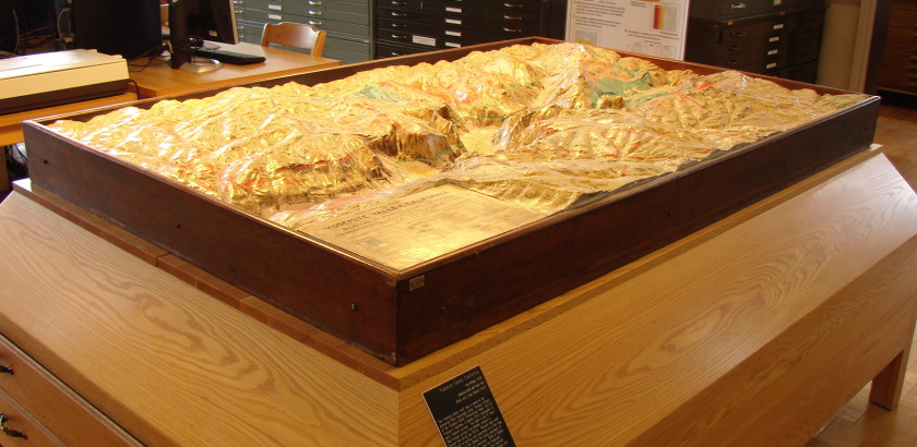
Relief models are three-dimensional objects with a thematic map overlay. Models are the most effective way to create spatial awareness and to display large, complex data sets so that the viewer can immediately see patterns and connections—a field we now call “data science.” Historic relief models from 1860-1930 were about 2-6 feet wide with a carved plaster terrain. After the 1930s, flexible rubber, foam, and plastic materials were employed by the military for portable models. After the 1970s, with access to new space imagery, digital relief models became the standard.
The primary commercial modelmaker was Edwin E. Howell (1845-1911), the owner of a nationwide business that supplied geology samples, relief models, and lecture slides. Details about Howell are in “A Wilderness of Rocks” and in the forthcoming biography, “Edwin E. Howell.” Others were created by university, museum, government, and business craftsmen. The military has always been largest producer and consumer of relief models, from the 1700s to today.
How were relief models constructed?
Making a historic relief model begins with its purpose, its story to tell. That purpose defines the size, scale, and content of the overall model. Many relief models were designed to be viewed at tabletop height to give the closest feeling of being there yourself in miniature. The modeler then chooses the map theme, such as colors and data, to organize and create patterns for the viewer. Many sketches are made. Photographs are marked up. Then a basemap containing the geographic area is selected as a master map. These planning steps continue today, even with 3D printing.
The modeler marks up a basemap with contour line symbols into a column-row grid. Then the horizontal scale is determined, such as 1 inch across on the model is equal to 100 miles in reality. Next, the marked-up paper map is enlarged to fit the finished size of the model. Then the vertical scale of the model needs to be determined, which is the ratio of an inch in height on the model equals feet above sea level in reality. Vertical scale is determined by first calculating the highest and lowest points in feet above sea level. For example, a common contour map might have 50 feet vertically between lines, but on the finished model that same 50 feet would be an imperceptible 6/100th of an inch. Too flat and the model is uninteresting. Too exaggerated and the model is distorted.
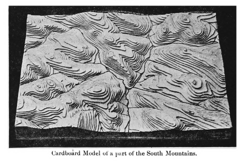
Cardboard was cut out along map contour lines, stacked into 3D terrain, and validated for accuracy. Figure from the book “A Wilderness of Rocks: the Impact of Relief Models on Data Science” by Melanie McCalmont.
Building up the relief
Building up the model starts with cutting along the contour lines of the enlarged paper map. The contour slices are glued onto sheets of hard cardboard or light wood. The material is selected in varying thicknesses so that, when stacked in singles or doubles, each layer would equal an increment of elevation. Alternately, if cutting up the basemap is not an option, the modeler can “pounce” the line, or poke tiny holes with a pin along the contour line on tracing paper, and then rub chalk over the holes so that the line transfers to the cardboard. Each contour is carefully numbered for reassembly. A model might require thousands of these pieces.
The cardboard contours are cut out with a sharp knife or jigsaw, then stacked according to the grid number. Next comes the detailed modelling. The cardboard contours are covered with a clay-wax hybrid modeling material. The modeling clay is applied to the cardboard contours in sections, filling in the step crevices. Using photographs, sketches, and notebooks, the modelers uses sculptor’s tools to carve the landscape into its final shape.
Making a negative
Once the master is accurate, a negative mould is made from the master. After the mould dries, it’s lifted and released from the waxed master terrain underneath. This step was the trickiest. Howell wrote that even a small area not properly waxed or a particularly complex terrain would seize a mould and it would not release cleanly from the master. If it stuck, the entire plaster mould—sometimes 6 feet or more on a side—has to be carefully chiseled off, the master terrain cleaned and re-waxed, and the moulding process started over.
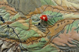
Detail of the “Black Hills of South Dakota” relief model by E. E. Howell at the South Dakota School of Mines and Technology, Rapid City, SD [http://www.sdsmt.edu/]
Making copies
The finished relief model is made from the negative mould. The mould is heavily waxed. Then, an internal support grid of heavy-gauge wire is formed across the mould’s shape. A box frame and support stringers is finally built around the mould. The plaster mix is poured into the box over the wire support mesh. After drying, the final model is released from the mould, sanded and prepared for painting. This finished product is a copy of the original sculpted clay model.
Painting the thematic map layer usually took about 2-3 weeks for a reproduction model. Artist’s paints and varnishes were used. It’s interesting to note that women were the chief painters in Howell’s busy shop. For large areas and basecoats, a paint atomizer was used. Text was the final addition in black and, as the last step, special art glazes and decorative frames were applied.